OBSOLETE
Please see the new Vega color range of instruments for the Infinity replacement
The Stratomaster Infinity range consists of fifteen 2 1/4" microprocessor based instruments.
Using a custom made, high resolution graphics display, these instrument provide excellent daylight readability, even in direct sunlight. In addition they all have built in backlighting making them easy to read at night time.
It includes a rotary control plus 2 independent keys for easy menu navigation and to access specific instrument features.
The infinity range also has a wide supply voltage range of 8 to 30V DC with with built in reverse and over voltage protection.
The Infinity series features
- Standard 2 1/4” aircraft enclosure (Can be front or rear mounted)
- Rotary control plus 2 independent buttons for easy menu navigation and user input
- Alarm output as well as a red LED illuminates for alarm notification
- Large backlit graphic LCD with adjustable contrast
- Multiple display screens (model dependent)
- On board voltage reversal and over voltage protection for harsh electrical environments
- Wide supply voltage range (8 to 30V DC)
- Light weight design
- Field upgradeable firmware
- 1 year limited warranty
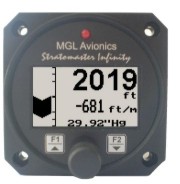
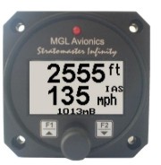
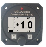
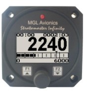
ALT-1 (Precision encoding altimeter and VSI indicator)
![]() ALT-1 Manual ( Revision
1.09)
ALT-1 Manual ( Revision
1.09)
Latest Firmware Revision: 1.12
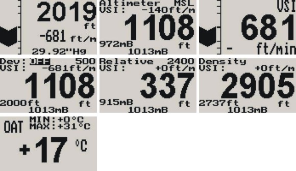
The ALT-1 is a 2 1/4” instrument that contains a precision encoding altimeter and a wide range vertical speed indicator. The altimeter conforms to ANSI standard atmosphere rules from –1000 ft up to a maximum of 40 000 ft. The altimeter includes an encoding serial output that when used in combination with MGL Avionics CNV-AT, provides a parallel Gillham code interface for transponders. The altimeter can display altitude in feet or meters, local pressure can be set in millibars or inches of mercury.
The onboard VSI indicator is altitude compensated and can be
displayed in either feet/minute (ft/min) or meters/second (m/s). It also
offers a digital readout with a wide range from +/-20 ft/min to as high as
+/-10 000 ft/min, it also offers a logarithmic analog display with a
+/-2000 ft range. The VSI can be calibrated by the user once the
instrument has been installed in the aircraft.
In addition the ALT-1 provides an OAT sender which is used in the determining the density altitude of the aircraft. The ALT-1 can also be used to measure relative altitude as well as it has a facility for the pilot to enter a reference altitude and deviation band that has to be kept.
- Precision altimeter for –700 ft up to a maximum of 40 000 ft
- Provides altitude encoder data on airtalk (serial) output, which can be converted by a MGL Avionics CNV-AT converter to a parallel Gillham code interface for transponders .
- The altimeter can display altitude in feet or meters, local pressure can be set in millibars or inches of mercury.
- Contains a wide range VSI indicator from +/-20 ft/min to as high as +/-10 000 ft/min
- VSI units can be in feet/minute (ft/min) or in meters/second (m/s)
- Records the maximum and minimum OAT (outside air temperature) and maximum altitude reached in permanent memory
- Records maximum and minimum OAT in temporary memory since instrument power up
ALT-2 ( Precision encoding altimeter and VSI indicator with a serial RS232 transponder output )
![]() ALT-2 Manual
(Revision 1.05)
ALT-2 Manual
(Revision 1.05)
Latest Firmware Revision: 1.05
The ALT-2 is a 2 1/4” instrument that contains a precision encoding altimeter and a wide range vertical speed indicator. The altimeter conforms to ANSI standard atmosphere rules from –700 ft up to a maximum of 40 000 ft. The ALT-2 outputs various formatted RS232 serial data protocols compatible with serial input transponders such as that from Garmin, Magellan, Northstar, Trimble, Microair etc. The altimeter can display altitude in feet or meters, local pressure can be set in millibars or inches of mercury.
The onboard VSI indicator is altitude compensated and can be displayed in either feet/minute (ft/min) or meters/second (m/s). It also offers a digital readout with a wide range from +/-20 ft/min to as high as +/-10 000 ft/min, it also offers a logarithmic analog display with a +/-2000 ft range. The VSI can be calibrated by the user once the instrument has been installed in the aircraft.
In addition the ALT-2 provides an OAT sender which is used in determining the density altitude of the aircraft. The ALT-2 can also be used to measure relative altitude and it has a facility for the pilot to enter a reference altitude and deviation band that has to be kept.
- Precision altimeter for –700 ft up to a maximum of 40 000 ft.
- The ALT-2 outputs various formatted RS232 serial data protocols compatible with serial input transponders such as that from Garmin, Magellan, Northstar, Trimble, Microair etc.
- The altimeter can display altitude in feet or meters, local pressure can be set in millibars or inches of mercury.
- Contains a wide range VSI indicator from +/-20 ft/min to as high as +/-10 000 ft/min
- VSI units can be in feet/minute (ft/min) or in meters/second (m/s)
- Records the maximum and minimum OAT (outside air temperature) and maximum altitude reached in permanent memory
- Records maximum and minimum OAT in temporary memory since instrument power up
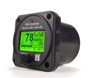
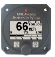
ASI-1 (Airspeed indicator (ASI) with automatic flight log)
![]() ASI-1
Manual (Revision
1.06)
ASI-1
Manual (Revision
1.06)
Latest Firmware Revision: 1.06
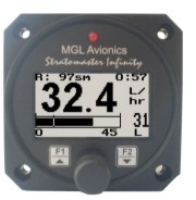
The ASI-1 airspeed indicator is a 2 1/4” instrument that provides a wide range airspeed indication in both digital and analog formats. Airspeed is based on the pressure generated by a pitot tube system and a static port is provided as well for use by high speed aircraft.
In addition, the ASI-1 provides a 24 entry automatic flight log that stores the duration of each of the last 24 flights, an air-distance trip counter and a current flight timer. Airspeed can be indicated in statute miles per hour (mph), kilometers per hour (km/h) or nautical miles per hour (knots) with the air-distance being displayed in corresponding units. The analog airspeed display can be scaled according to the aircrafts flying speed range and markers for Vs, Vf, Vno and Vne can be set. ASI sensitivity can be calibrated by the user to cater for errors caused by pitot tube placement.
- Measure airspeed from 16mph to 250mph and is well suited to slow aircraft due to very good sensitivity and linearity at low air speeds.
- Includes a 24 entry automatic flight log
- Includes an air-distance trip counter and a flight timer
- Airspeed units can be set to miles per hour (mph), kilometer per hour (km/h) or nautical miles per hour (knots)
- Contains a programmable low/high airspeed alarm
- Records maximum airspeed reached in permanent memory
- Analog bar graph indicating airspeed with markers for Vs, Vf, Vno and Vne
ASX-1 (Encoding aviation altimeter with serial output and airspeed indicator)
![]() ASX-1 Manual (Revision
1.06)
ASX-1 Manual (Revision
1.06)
Latest Firmware Revision: 1.11
The ASX-1altimeter/airspeed combo is a 2 1/4”
instrument based on a precision altimeter and a wide range, sensitive
airspeed indicator. The altimeter conforms to ANSI standard atmosphere
rules from –1000ft up to a maximum of 40 000 ft.
The altimeter includes an encoding serial output that, when used in combination with MGL Avionics CNV-AT, provides a parallel Gillham code interface for transponders. The altimeter can display altitude in feet or meters. Local pressure can be set in millibars or inches or mercury.
The airspeed indicator can show air speeds from 16 to
250 mph and is well suited for use in slow aircraft due to very good
sensitivity and linearity at low air speeds. The airspeed indicator as
well as altimeter can interface to a static port and the airspeed
indicator is based on a standard aviation pitot tube. The airspeed
indicator can be set to indicate speeds in statute miles per hour (mph),
kilometers per hour (km/h) or nautical miles per hour (knots) with the
air-distance being displayed in corresponding units. The airspeed
sensitivity can be calibrated by the user to cater for errors caused by
pitot tube placement. The ASX-1 also outputs airspeed information via the
airtalk protocol for interfacing to the Infinity FF-1 (fuel flow computer
for single or dual fuel tanks) and the SP-X (AHRS) instruments.
In addition the ASX-1 provides a 24 entry automatic flight log that stores the duration of each of the last 24 flights, an air-distance trip counter and a current flight timer. The ASX-1 is the ideal instrument for installations were panel space is at a premium.
- Precision altimeter for –700 ft up to a maximum of 40 000 ft
- Provides a parallel Gillham code interface for transponders when used in combination with the MGL Avionics CNV-AT.
- The altimeter can display altitude in feet or meters. Local pressure can be set in millibars or inches or mercury.
- Airspeed ranges from 16 to 250mph and is well suited to slow aircraft due to very good sensitivity and linearity at low air speeds. Airspeed can be displayed as IAS or a calculation based TAS.
- Includes a 24 entry automatic flight log
- Includes an air-distance trip counter and a flight timer
- Airspeed units can be in miles per hour (mph), kilometer per hour (kph) or nautical miles per hour (knots)
- Contains a programmable low/high airspeed alarm
- Records maximum airspeed and altitude reached in permanent memory
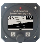
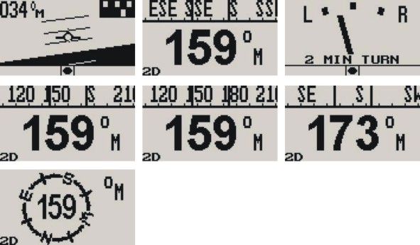
AV-1 (Artificial horizon and advanced magnetic compass indicator)
![]() AV-1 Manual (Revision 1.05)
AV-1 Manual (Revision 1.05)
Latest Firmware Revision: 1.10
The AV-1 is a 2 1/4” instrument that can be used as a
display interface for an artificial horizon reference system (AHRS) or as
an advanced digital compass, or both depending on which MGL Avionics
sensor packages is connected to the AV-1.
The AV-1 can be setup to display the
following:
- Compass with five different displays (requires MGL Avionics SP-2/6 sensor package)
- Horizon with or without slip indicator (requires MGL Avionics SP-3/4/5/7 sensor package)
- Turn and bank indicator (requires MGL Avionics SP-3/4/5/7 sensor package)
- Combined compass and horizon display with bank indicator and optional slip indicator (requires MGL Avionics SP2/6 & SP-3/4/5/7 sensor package)
You can also share sensor packages between various different size instruments eg. AV-2 units (these have a 3 1/8” display). For example you may want a 3 1/8” horizon display but a 2 1/4” compass/turn and bank indicator.
- Artificial horizon reference system (AHRS) display unit with slip indication as well as turn and bank indication.
- Advanced magnetic compass with course steering feature.
- Can be setup as an individual compass display, artificial horizon or both.
- The AV-1 is connected to the sensor packages by a simple 2 wire communication link. This allows for the optimum placement of the sensor packages in the aircraft.
- More then one AV-1 can be connected onto a airtalk link. This allows for displaying the compass, artificial horizon and the turn and bank indicator on different AV-1/2 units.
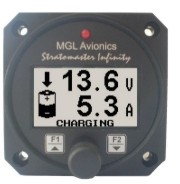
BAT-1 (Battery voltage and current monitor)
![]() BAT-1 Manual (Revision
1.05)
BAT-1 Manual (Revision
1.05)
Latest Firmware Revision: 1.05

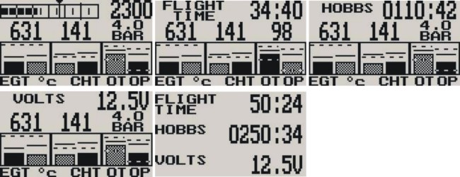
The BAT-1 is a 2 1/4” instrument used to monitor your aircrafts battery power supply. It can be used on lead-acid, NiCad batteries as well as gel cells. This instrument is very useful in determining your battery’s health, charging status, as well as the current load consumption of your aircraft.
The BAT-1 can be used in both 12V and 24V aircraft and can measure voltages up to 30V DC. The BAT-1 uses a standard 50 mV shunt to measure the current making the unit capable of measuring currents from 5A to 500A.The instrument contains a programmable low/high voltage alarm to automatically detect bad batteries and alternator failures.
- Measure voltage and current simultaneously
- Can measure voltages up to 30V (Compatible with both 12V and 24V aircraft supplies)
- Contains a programmable low/high voltage alarm to automatically catch alternator failures and bad batteries
- Includes a battery charge/discharge indication
- Choice of 3 display modes (volts only, current only, or dual current & voltage display)
- Records maximum volts, charge and discharge currents in permanent memory
- Analog bar graph indicating charge/discharge current
- BiLingual (English and French)
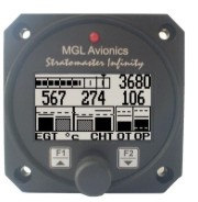
E-3 (Universal engine monitor)
![]() E-3 Manual (Revision 1.10)
E-3 Manual (Revision 1.10)
Latest Firmware Revision: 1.09
The E-3 universal engine monitor combines in one
compact 2 1/4” format instrument all that is needed to monitor the
majority of smaller aircraft engines from two-stroke ultra-light engines
to medium sized four strokes such as those from Rotax, Continental and
Lycoming. Most automotive engine conversions can also benefit from the use
of the E-3 engine monitor.
The E-3 can measure up to 4 EGT/CHT channels, a RPM input, a universal temperature sender input and a universal pressure sender input.
- 66 different engine setup configurations possible
- Universal, programmable rev counter (engine RPM) with digital and analog readout, with a programmable high alarm limit
- Programmable engine Hobbs meter (password protected) and running timer (flight timer) with automatic flight log
- Can monitor up to four programmable thermocouple channels for EGT and CHT probes with a user programmable high alarm limit
- A universal temperature sender input with a user programmable low and high alarm limits
- A universal pressure sender input with a user programmable low and high alarm limits
- Maximum recorded values for all measured values are stored in non-volatile memory
- High accuracy: Built in thermocouple linearization curves and cold junction compensation
- Thermocouple temperature probes can be common K,J or E type thermocouple probes
- Uses standard automotive temperature and pressure senders
- Special Rotax 912/914 engine monitor mode utilizing the standard built in Rotax NTC CHT probes
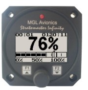
FF-1 (Fuel Management System)
![]() FF-1
Manual (Revision
1.12)
FF-1
Manual (Revision
1.12)
Latest Firmware Revision: 1.17
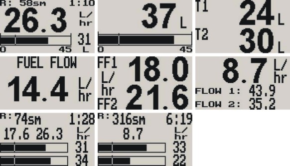
The FF-1 fuel management computer is a 2 1/4” instrument intended for efficient monitoring of fuel related information for single or dual fuel tanks onboard small aircraft and related applications.
The FF-1 unit can connect to one or two fuel flow senders, one or two fuel level senders or both. Full functionality is available with both senders or only with a fuel flow sender using calculated fuel levels based on fuel usage. Differential fuel flow calculations are also supported for fuel return systems. Fuel injector systems are also supported.
Standard automotive fuel level senders can be used,
even with odd shaped tanks due to a comprehensive, multi-point calibration
system. Most fuel flow senders can be used and the K-factor of the sender
can be entered into the system for simple calibration. MGL Avionics
supplies a lightweight dual range fuel flow sender that is ideally suited
for the FF-1.
In addition, the FF-1 can use the airspeed (via the airtalk cable connected to a Infinity ASI-1/ASX-1 indicator) or actual ground speed (by using the optional FF-1 to RS232 GPS cable connected to a RS232 NMEA enabled GPS receiver) to determine fuel range.
- Advanced fuel computer with 13 different modes of operation
- Supports single or dual fuel tanks
- The FF-1 can connect to one or two fuel flow senders, fuel level senders or fuel injectors
- Differential fuel flow calculations are also supported for fuel return systems
- The FF-1 has the ability to connect to an ASI-1/ASX-1 or a NMEA enabled GPS receiver for range based calculations. It can also accept a manually entered estimate cruising speed if an ASI-1/ASX-1 GPS is not available.
- Standard automotive fuel level senders can be used, even with odd shaped tanks due to a comprehensive, multi-point calibration system
- Bilingual support (English and French)
The Infinity FF-1 / Velocity FF-3 and Flight-2 has the ability to be connected to a NMEA enabled RS232 GPS receiver to allow the use of actual ground speed in determining the fuel range (See the relevant instrument manual for more information).
The NMEA enabled RS232 GPS receiver must be able to output a GPRMC message (The Recommended Minimum sentence defined by NMEA for GPS/Transit system data).
![]() GPS NMEA Interface Cable
manual
GPS NMEA Interface Cable
manual
GF-1(+- 10G Tilt compensated dual range G-force meter)
![]() GF-1 Manual (Revision 1.04)
GF-1 Manual (Revision 1.04)
Latest Firmware Revision: 1.05
The GF-1 is a 2 1/4” g-force meter capable of measuring G-forces exerted in an aircraft up to +-10G. The forces acting on the aircraft is easily seen on a large backlit graphics display both numerically and graphically.
The GF-1 also has the facility to record maximum G-forces obtained in permanent memory as well as it has a temporary memory to record G-forces reached from the time of power up. It also features 2 independent cycle counters to capture the amount of times a preset force has been exceeded.
The GF-1 is able to measure G-forces even if the instrument is not mounted exactly in the vertical axis of the aircraft.
- Typical, accurate range up to 20G (From -10Gto +10G)
- Records maximum measured forces in permanent memory (Both positive and Negative G-forces), with password protected reset facility
- Two independent cycle counters record the number of times a preset force has been exceeded.
- Temporary memory for maximum positive and negative G-forces encountered (typically during a flight)
- Clear large readable G-force numerical value (10G positive and negative)
- Scalable graphic analog display of force acting on the aircraft
- 2 axis design of the instrument allows mounting in sloped panels (i.e. panel not exactly vertical)
- Quick calibration function for operation at temperature extremes using Earth gravity.
- Bilingual support (English and French)
MAP-1 (Universal pressure indicator)
![]() MAP-1 Manual (Revision 1.04)
MAP-1 Manual (Revision 1.04)
Latest Firmware Revision: 1.08

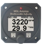
The MAP-1 is a 2 1/4” instrument which can measure pressures in the range of 0.25 bars (3.6 PSI) to 2.5 bars (36.2 PSI) as well as simultaneously display RPM from a universal RPM input.
Pressure can be displayed
in millibar, bar, PSI, kg/cm2, inches of Mercury, millimeters of Mercury,
kilopascal (KPA) or atmospheres. The pressure display is also available in
the form of an analog bar graph with user selectable sensitivity if the
RPM input is not needed. The MAP-1 is primarily intended as a manifold
pressure gauge, however, due to the universal nature of this accurate
instrument it can be used for many other applications as
well.
In addition the MAP-1
provides a 24 entry automatic flight log that stores the duration of each
of the last 24 flights. It also has a Hobbs meter (can be set to the
current engine time) which is password protected, an engine running
timer/flight timer and a programmable maintenance timer to schedule
routine engine maintenance.
The MAP-1 also features a
programmable low/high alarm for pressure as well as for RPM and it also
records the maximum Pressure and RPM reached in permanent
memory.
Typical applications include:
Engine manifold pressure, turbo boost pressure, barometer, fuel or oil pressure gauge (with additional isolation kit), pressure reference or airfoil research and testing
- Universal pressure and RPM indicator
- Can Measures RPM from 0 to 20000 RPM
- Can measure pressures in the range of 0.25 bars (3.6 PSI) to 2.5 bars (36.2 PSI)
- Pressure can be displayed in millibar, bar, PSI, kg/cm2, inches of Mercury, millimeters of Mercury, kilopascal (KPA) or atmospheres
- Contains a programmable low/high Pressure and RPM alarm
- Records maximum pressure and RPM reached in permanent memory
- Includes a 24 entry automatic flight log
- Includes a settable Hobbs meter (password protected) and an engine running timer/flight timer
- Contains a programmable maintenance timer for scheduled routine engine maintenance
- Scalable analog pressure bar graph
RTC-2 (Aviation Real Time Clock (RTC) & Outside Air Temperature (OAT) display)
![]() RTC-2 Manual (Revision 1.06)
RTC-2 Manual (Revision 1.06)
Latest Firmware Revision: 1.06
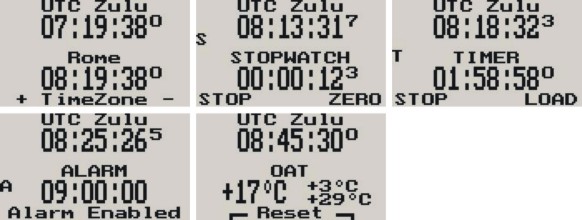
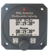
The RTC-2 is a 2 1/4” aviation Real Time Clock
featuring a two time zone system, stopwatch, countdown timer, alarm and
OAT (Outside Air Temperature) display. It is primarily intended to show
UTC time (also known as Greenwich Mean Time, GMT or Zulu time) together
with a local time to facilitate ordinary ATC time reporting.
Each time zone may be programmed with an additional hour offset to allow for summer time or similar variances. Local offsets may be added or subtracted. Stopwatch and Timers can be operated simultaneously to a programmable alarm, making the RTC-2 particularly suitable for sport flying competitions. OAT can be shown in either degrees Celsius or degrees Fahrenheit. The RTC-2 can be setup to automatically or manually alternate between the different time display screens and the OAT display. Time is maintained by an internal lithium battery which can be replaced by the user.
- Features a 2 time zone system, stopwatch, countdown timer, alarm and OAT (outside air temperature) display
- Stopwatch and timers can operate simultaneously to a programmable alarm
- Local time offsets can be added or subtracted e.g. summer time or similar variances
- OAT can be shown in degrees Celsius or in degrees Fahrenheit
- Records maximum and minimum OAT in permanent memory
- Replaceable lithium battery
RV-1 (Universal engine RPM and rotor RPM indicator)
![]() RV-1 Manual (Revision 1.10)
RV-1 Manual (Revision 1.10)
Latest Firmware Revision: 1.07

The RV-1 universal engine RPM and rotor RPM unit is a
2 1/4” instrument providing a universal RPM counter that can be adapted to
a variety of roles. Typical uses are engine RPM displays or Helicopter /
Gyroplane Rotor RPM displays.
The RV-1
displays RPM in a digital readout as well as in a scalable analog bar
graph display. In addition the RV-1 provides a 24 entry automatic flight
log that stores the duration of each of the last 24 flights. It also has a
The RV-1 also features a programmable RPM high alarm as well as it records the maximum RPM reached in permanent memory.
- Measures RPM from 0 to 20000 RPM.
- Includes a 24 entry automatic flight log
- Includes a settable Hobbs meter (Password protected) and an engine running timer/flight timer.
- Contains a programmable low/high RPM alarm
- Contains a programmable maintenance timer for scheduled routine engine maintenance
- Records maximum RPM reached in permanent memory
- Scalable analog bar graph indicating RPM
RV-2 (Universal turbine RPM / RPM factor display)
![]() RV-2
Manual (Revision 1.01)
RV-2
Manual (Revision 1.01)
Latest Firmware Revision: 1.01

The RV-2 is a 2 1/4” instrument providing
a universal turbine RPM display that can be adapted
to a variety of roles. Typical uses are turbine RPM displays for N1 or N2.
The RV-2 can use standard tach genies but can also be used with almost any
electrical signal related to turbine RPM.
The RV-2 displays RPM in a digital readout as well as
in a scalable analog bar graph display. In addition the RV-2 provides a 24
entry automatic flight log that stores the duration of each of the last 24
flights. It also has a
The RV-2 also features a programmable RPM high alarm as well as it records the maximum RPM reached in permanent memory.
- Measures RPM from 0 to 99999 RPM or a factor in percent relative to a value that can be entered into the unit. For example 50000 RPM = 100%
- Includes a 24 entry automatic flight log
- Includes a settable Hobbs meter (password protected) and a turbine running timer/flight timer
- Contains a programmable high RPM alarm
- Contains a programmable maintenance timer for scheduled routine engine maintenance
- Records maximum RPM reached in permanent memory
- Scalable analog bar graph indicating RPM
- External alarm output as well as a red LED illuminates when the alarm has been activated
TC-1 (4 Channel thermocouple indicator)
![]() TC-1 Manual (Revision 1.09)
TC-1 Manual (Revision 1.09)
Latest Firmware Revision: 1.09
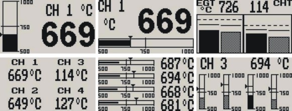
The TC-1 thermocouple display unit is a 4 channel 2
1/4” instrument that contains all the features necessary to monitor EGTs
and CHTs. The instrument is fully programmable by the user resulting in
the most flexible solution available. It contains 6 different display
screens to allow easy customization. The TC-1 can be configured to group
EGTs/CHTs to common settings or each thermocouple channel can be
independently setup for temperature ranges as well as alarms and probe
types.
The TC-1’s high accuracy is due to its built in thermocouple linearization curves and cold junction compensation techniques. Temperature probes can be common K, J or E type thermocouple probes as used in CHT or EGT sensors. Temperatures can be displayed in degrees Celcius or degrees Fahrenheit from -270ºC to 1370ºC (-454ºF to 2498ºF). Each channel also offers a programmable high alarm.
The TC-1 also records maximum temperatures reached for each channel in permanent memory.
- 6 different display modes
- Supports J, K and E thermocouple probes
- Temperatures can be displayed in degrees C or degrees F from -270 ºC to 1370ºC (-454ºF to 2498ºF).
- High accuracy: Built in thermocouple linearization curves and cold junction compensated
- Records Maximum temperatures reached for each channel in permanent memory
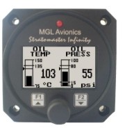
TP-1 (Universal Temperature/Pressure gauge)
![]() TP-1
Manual (Revision 1.10)
TP-1
Manual (Revision 1.10)
Latest Firmware Revision: 1.14
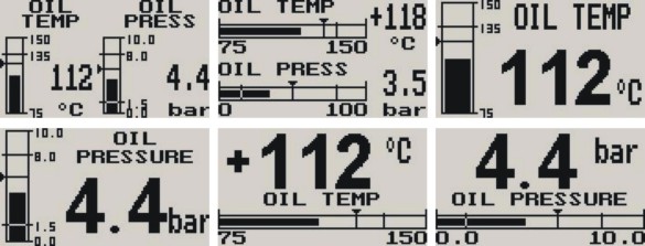
The TP-1 is a 2 1/4” dual channel
temperature/pressure gauge with universal inputs that can interface to
many sensors such as oil temperature, coolant temperature, oil pressure,
fuel pressure, manifold pressure, boost pressure and many more.
The TP-1 gauge can be setup for a single, dual
or combination temperature / pressure display.
Temperature can be measured using standard
automotive resistive senders (e.g. VDO) as well as the MGL Avionics
precision LM335 semiconductor sensor. Pressure can be measured using
standard automotive resistive senders (e.g. VDO), Rotax 4-20mA senders as
well as 0-5V output pressure senders (e.g. UMA). In addition the
temperature and pressure inputs can be programmed to a user defined curve
for custom senders.
Both the temperature and pressure readings have a programmable low and high alarm. This results in a contact closure that is typically used to switch a warning lamp on. The TP-1 also records the maximum temperature and pressure values reached in permanent memory.
- Dual channel universal input temperature and pressure gauge
- Temperature can be measured using standard automotive resistive senders (e.g. VDO) as well as the MGL Avionics precision LM335 semiconductor sensor
- Pressure can be measured using standard automotive resistive senders (e.g. VDO), Rotax 4-20mA senders as well as 0-5V output pressure senders (e.g. UMA)
- Temperature and pressure inputs can be programmed to a user defined curve for custom senders
- Can be setup for a single, dual or combination temperature / pressure display.Both temperature and pressure readings have a programmable low and high alarm Records maximum temperature and pressure reached in permanent memory
- Supports Rotax 4-20mA pressure sender as used in 912/914 engines
- Standard 2 1/4” aircraft enclosure (can be front or rear mounted)
- Rotary control plus 2 independent buttons for easy menu navigation and user input
- External alarm output as well as a red LED illuminates when the alarm has been activated
- Large backlit graphic LCD with adjustable contrast
- Wide input supply voltage range of 8 to 30V DC with built in voltage reversal and over voltage protection for harsh electrical environments
- Light weight design
- 1 year limited warranty