AHRS-1
Artificial Horizon and Magnetic Compass Indicator
 Vega AHRS-1 / MAG-1 Manual
|
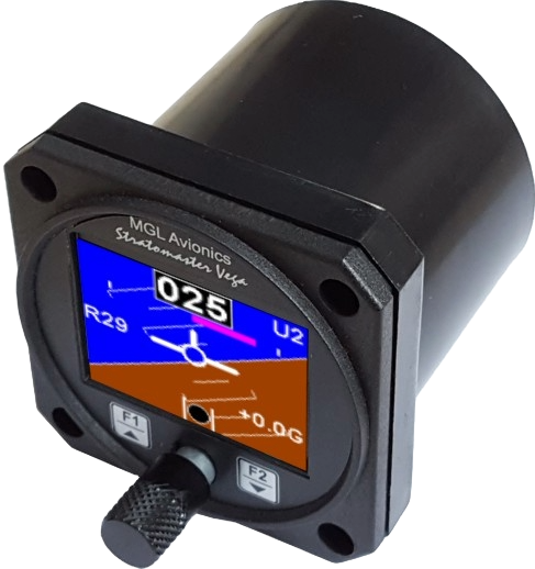
AHRS-3
Self Contained Artificial Horizon and Magnetic Compass Indicator
Vega AHRS-3 / MAG-1 Manual
|
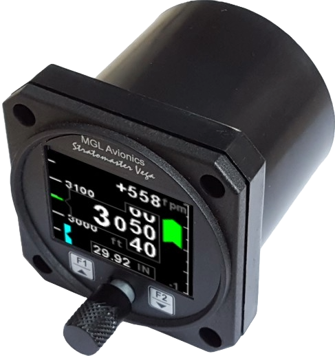
ALT-5
Altimeter and Vertical Speed Indicator (VSI)
Vega Alt-5 Manual |
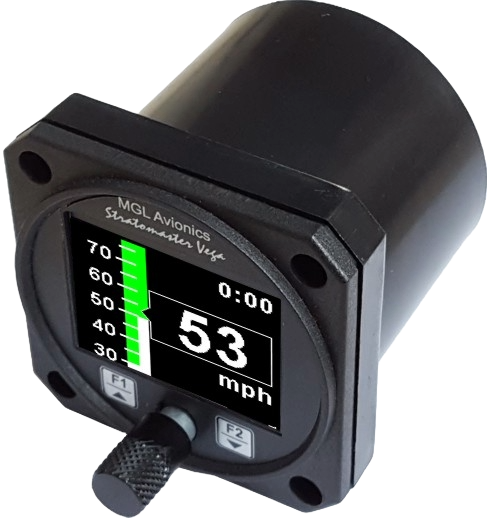
ASI-4
Airspeed Indicator
Vega ASI-4 Manual
|
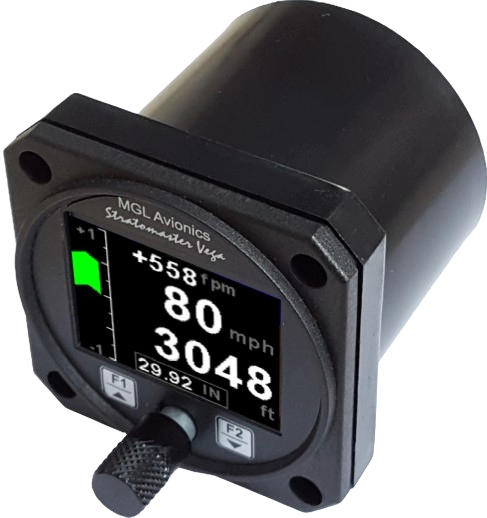
ASV-1
Altimeter, Airspeed (ASI) and Vertical Speed Indicator (VSI)
Vega ASV-1 Manual
|
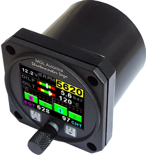
EMS-1
Universal Engine Monitor
Vega EMS-1 Manual |
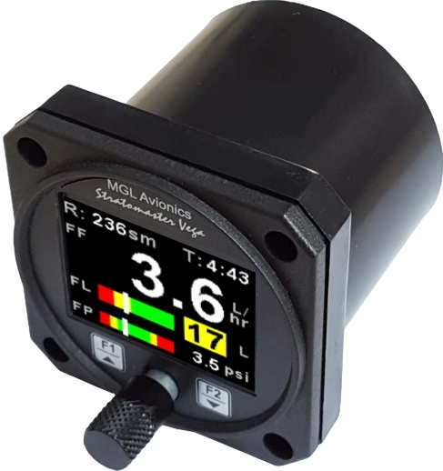
FF-4
Fuel Computer
Vega FF-4 Manual
|
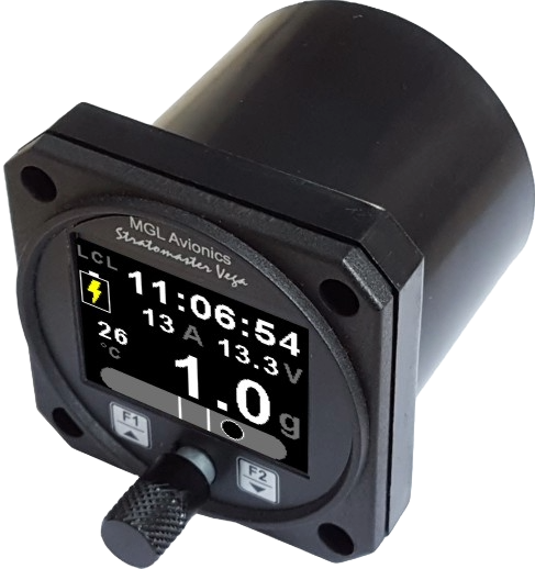
INFO-1
Information Display (G-Force meter, UTC and Local Time, Slip
Indicator, Outside Air Temperature (OAT), Battery Voltage, Current and
charge display, Flight Timer & Flight Log, Stopwatch, Coutdown Timer and
Alarm)
Vega INFO-1 Manual
|
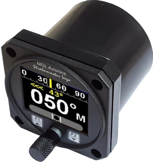
MAG-1
Magnetic Compass Indicator
Vega MAG-1 Manual |
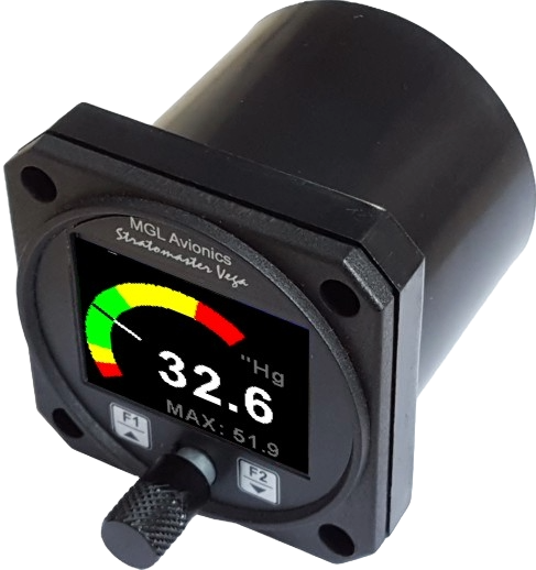
MAP-3
Manifold Pressure and RPM Indicator
Vega MAP-3 Manual
|
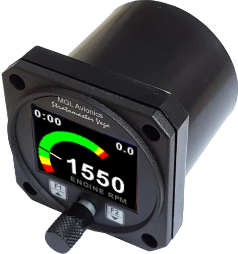
RPM-1
Universal Engine / Rotor RPM Indicator
Vega RPM-1 Manual |
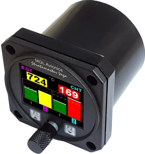
TC-4
4 Channel Thermocouple (EGT/CHT) Indicator
Vega TC-4 Manual
|
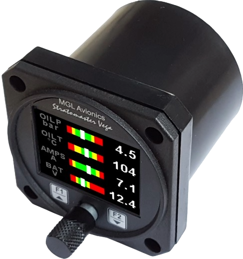
TP-3
4 Channel Universal Analog Input
(Pressure / Temperature / Current / Volts) Indicator)
Vega TP-3 Manual
|
LOG-1
Blaze / Vega Serial Datalogger
Blaze / Vega Serial Data logger Manual
 LOG-1 / LOG-2
Firmware (Version 1.08)
LOG-1 / LOG-2
Firmware (Version 1.08)
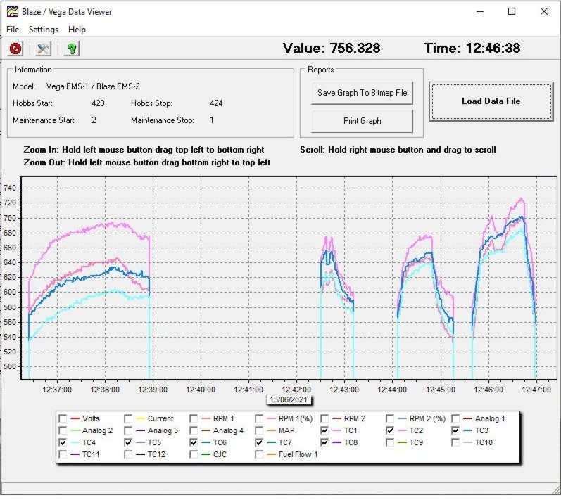
Blaze / Vega Data Viewer Software (Version 1.02)
 |
|
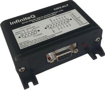
CNV-ALT
Serial altitude to parallel Gillham code
converter for mode C transponders
CNV-ALT Manual
CNV-ALT Firmware (Version 1.00)
CNV-ALT Garmin Protocol Firmware
CNV-ALT Icarus
Firmware |
|