Help with interface board for RDAC X-B

Post here for anything that does not fit any of the categories below. Any topic related to MGL and flying welcome.
Forum rules
Please keep your posts friendly and on topic. No politics or discussions of a controversial nature not related to our favorite subject of flying and avionics. Offending posts may be removed or moderated.
Post Reply
eengineer
Posts: 3
Joined: Tue Mar 07, 2023 8:56 am

Help with interface board for RDAC X-B

Post by eengineer »

I received RDAC X-B as a gift.
But for some reason the equipment is different from those that I find in the photo on the Internet.
It's as if there is no interface board.
https://support.michiganavionics.com/po ... -xd-manual
three
three
RDAC_X_B.jpeg (179.21 KiB) Viewed 251 times
I disassembled the case, powered the LDO(L7805) with 9 volts and do not receive any data via the RS-232 protocol
two
two
photo1713123931.jpeg (104.25 KiB) Viewed 251 times
I had another RDAC Vb module, so I power it with 9 volts in the same way, and it outputs data about the PC-232 protocol to the Stratomaster Ultra Horizon XL device.
And when I connect the motor to the RDAC Vb block, I can see the number of revolutions on the Stratomaster Ultra Horizon XL device.
https://www.stratomaster.eu/desktopdefa ... &tabid=188
one
one
photo1713123931 (2).jpeg (91.68 KiB) Viewed 251 times
I would like to figure it out and, if necessary, repair the RDAC X-B.
Help with advice.
rainier
Site Admin
Posts: 647
Joined: Fri Aug 28, 2020 7:03 pm

Re: Help with interface board for RDAC X-B

Post by rainier »

Is your LED on the RDAC flashing ?
eengineer
Posts: 3
Joined: Tue Mar 07, 2023 8:56 am

Re: Help with interface board for RDAC X-B

Post by eengineer »

rainier wrote: Wed Apr 17, 2024 1:57 pm Is your LED on the RDAC flashing ?
The problem is that the LED does not light up and does not blink at all.
Although +5V power is supplied to the board and the MCU.
Perhaps the microcontroller has become unusable, but I can replace it, but I couldn’t find the firmware anywhere.
I can write my own code for MCU, but all the functions of the device will not be implemented as intended.
I also discovered that the inductor was burning, but overall it is still working.
Coil_burned.jpeg
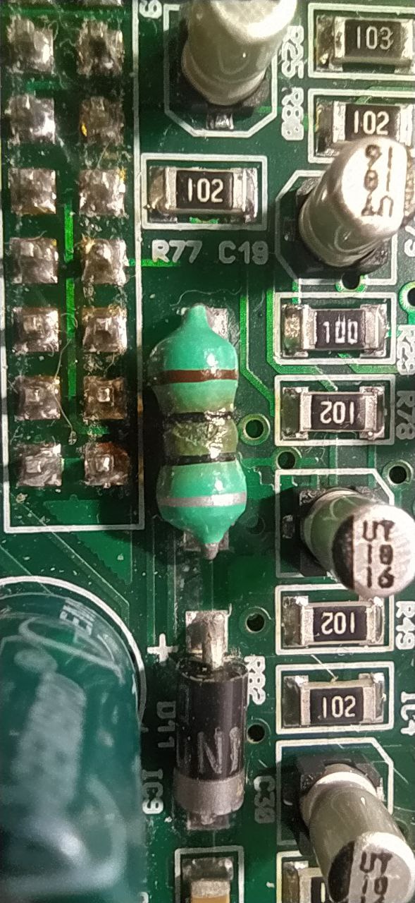
Coil_burned.jpeg (174.8 KiB) Viewed 230 times
I'm trying to ring all the circuits on the board and draw them in the diagram to make it clear and convenient to look for a fault.
MCU_LED.png
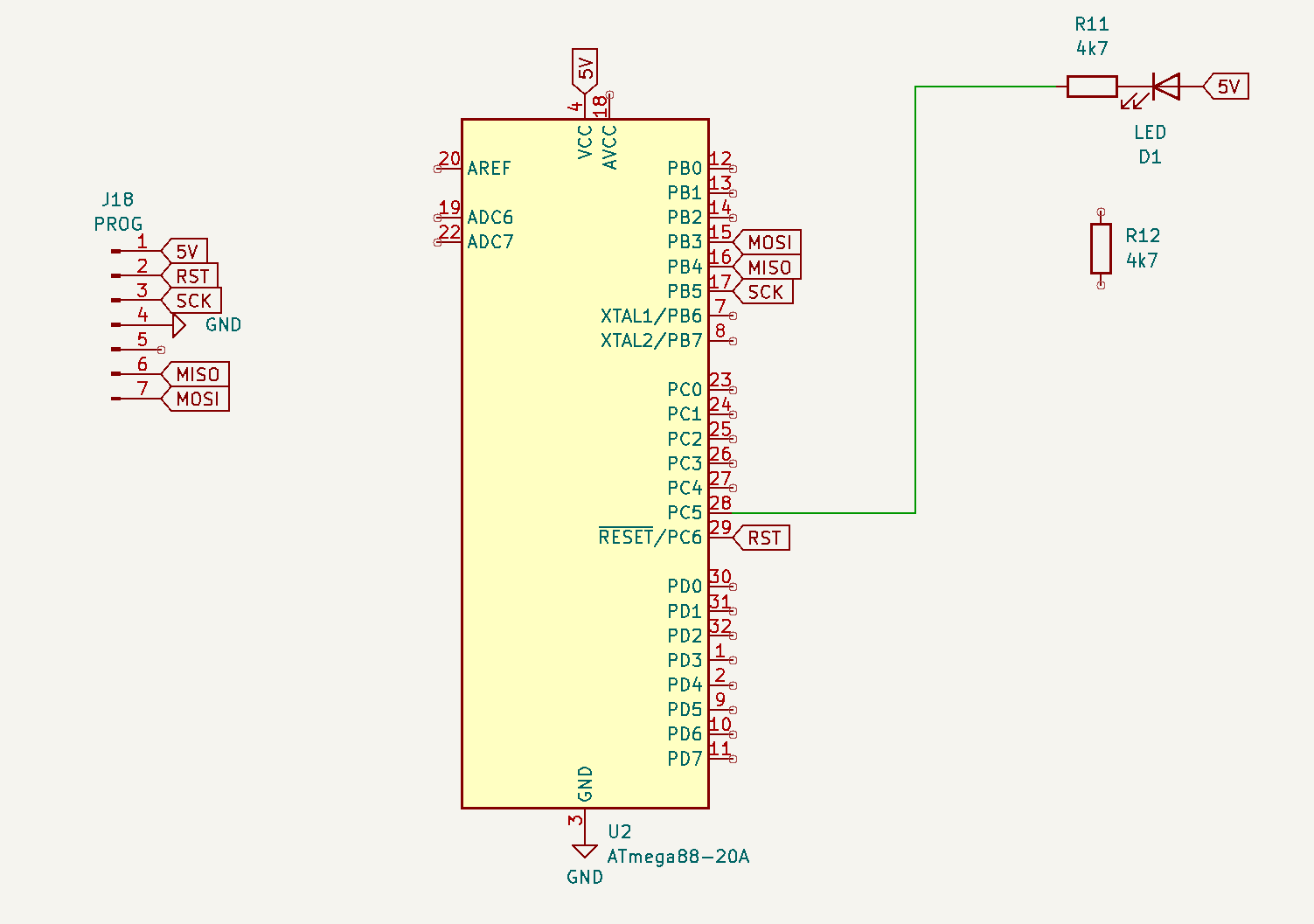
MCU_LED.png (25.13 KiB) Viewed 230 times
I haven't connected anything to the board's periphery yet.
As far as I understand from the documentation on the RDAC-Xb, when power is applied, the LED should blink, indicating a lack of communication.
Board.png
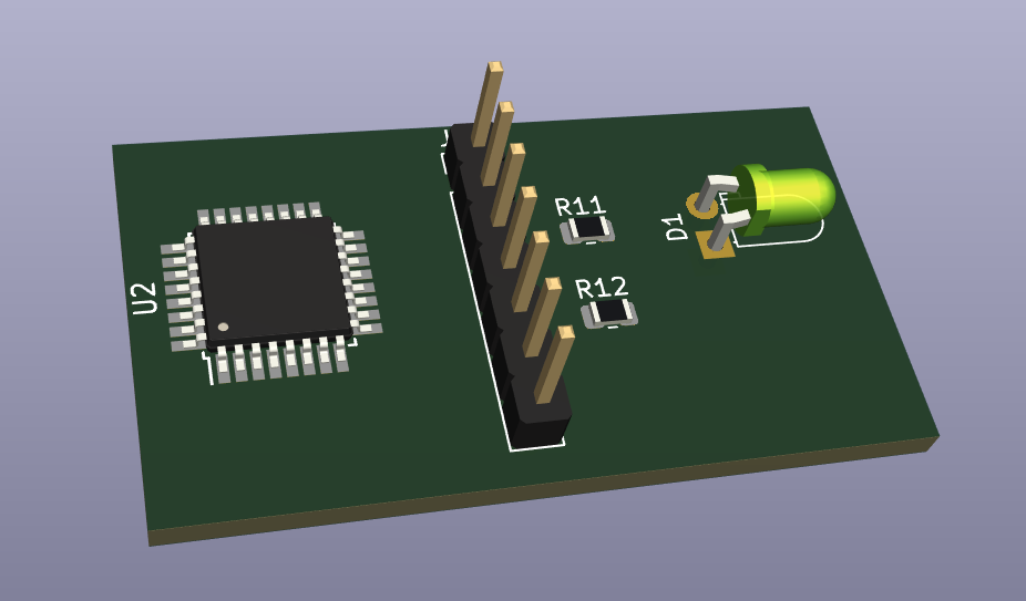
Board.png (58.55 KiB) Viewed 230 times
Image
But, as I wrote above, it feels like the bottom board, on which there were connectors and contacts for connecting sensors, has disappeared.
I wonder what format the protocol uses to transmit data.
Everywhere it is written that this is a RS232 protocol.
Please tell me, Can I receive data via a USB-TTL converter?
https://www.mglavionics.co.za/Docs/RDAC ... otocol.pdf
I would really appreciate your help.
rainier
Site Admin
Posts: 647
Joined: Fri Aug 28, 2020 7:03 pm

Re: Help with interface board for RDAC X-B

Post by rainier »

The LED will flash at 1Hz when the CPU is running.

If you have supply voltage at the CPU, the reset line is logical high, I'd be pretty sure that CPU is history - if you can find a replacement (make sure it is exactly the same) contact me privately and I'll send you the binary to flash to the CPU. You will also have to do some calibration and I'll tell you how to do that. You will need a 24.9mV DC supply for that (low impedance or a resistive divider and multimeter to confirm correct voltage).

Rainier
eengineer
Posts: 3
Joined: Tue Mar 07, 2023 8:56 am

Re: Help with interface board for RDAC X-B

Post by eengineer »

rainier wrote: Mon Apr 22, 2024 10:40 am The LED will flash at 1Hz when the CPU is running.

If you have supply voltage at the CPU, the reset line is logical high, I'd be pretty sure that CPU is history - if you can find a replacement (make sure it is exactly the same) contact me privately and I'll send you the binary to flash to the CPU. You will also have to do some calibration and I'll tell you how to do that. You will need a 24.9mV DC supply for that (low impedance or a resistive divider and multimeter to confirm correct voltage).

Rainier
On the pin of the PC6/RESET microcontroller there is 4.5 volts, which corresponds to logical 1.
Below is a diagram that I was able to draw from the board.
Schematic.png
Schematic.png (25.49 KiB) Viewed 165 times
I still think this microcontroller(ATmega88-20A) is fine
photo_ATmega88-20A.jpeg
photo_ATmega88-20A.jpeg (115.03 KiB) Viewed 159 times
but I also bought a similar replacement, if there is firmware, I can download it.
As far as I understand, from the output of PD1 (TXD), the data received by the microcontroller and converted into the MGL protocol is supplied in UART format to an optotransistor, and data can be obtained from the PL2 connector.
ATmega88-20A.png
ATmega88-20A.png (104.03 KiB) Viewed 165 times
But unfortunately, I didn’t have an interface board with convenient terminals in the kit.
P.S.
I wrote to you in a personal message.
Post Reply